
LabLearner Discussion: Work and Simple Machines
Intermediate+
 LabLearner Discussions are designed for you to sit and discuss science topics with your child/student. Each slide below contains rich content to stimulate intelligent discussions with your student, regardless of their age. Directed discussion is one of the most powerful ways we can interact with each other. Start with the first slide then move to the next slide below it as your discussion proceeds. Give it a try with your student.
Slide 1

In this Science Discussion, you and your child will discuss force and work. You will then learn about the different common simple machines. Your student may be surprised at how many of these machines they come in contact each day.
Slide 2

This slide introduces the concept of work. The equation at the top simply states that work is equal to the force being applied, multiplied by the distance over which the force will be exerted.
What direction is the force acting? It is obvious that the person pushing the box in the illustration is applying force in the direction of the arrow (from left to right).
Are there other forces acting on the box besides the person pushing? Yes. The force of gravity is pushing down on the box. Also, the floor itself exerts a force on the box called friction that works against the sliding of the box over it. Therefore, for the box to move, the person pushing must overcome these other forces.
Units: Force (F) is measured in Newtons (N) and can be determined using an instrument like a spring scale. Distance is measured in meters (m). So work (F x d), has units of Newton-meters. One Newton-meter is called a Joule.
Slide 3

This slide simply lists the six common simple machines; the lever, wheel and axle, wedge, inclined plane, screw, and pulley. You can discuss other examples of these simple machines. Keep in mind that simple machines may be only a part of a larger “machine”. For example, the go-cart pictured here is shown as an example of a wheel and axel (both the wheels and tires themselves as well as the steering wheel), but they are both components of the go-cart itself.
Simple machines often help us do work by providing mechanical advantage (MA). This is an important concept and is discussed further on the next slide.
Slide 4

Simple machines do not reduce the total amount of work, but rather increase mechanical advantage (MA). Increased mechanical advantage makes work seem easier to us but does not actually change the amount of work done.
A good way to illustrate mechanical advantage is to think about an inclined plane like the one pictured at the bottom of this slide. In this example, a 750N (about 75kg or 165 pound) box must be lifted to a height of 1 meter. Instead of lifting it straight up 1 meter, which might be very difficult or impossible, it is much easier to push it up the inclined plane. However, using the inclined plane results in us having to move the box 5 times further! Either way, the box must still be lifted the same distance of 1 meter. Therefore, the work done is the same regardless of how we do it.
When we talk about simple machines during this LabLearner Science Discussion, we will often speak in terms of the mechanical advantage they provide.
Slide 5

This slide shows examples of tools that utilize the concept of the lever. One of the most common images of a lever is when a long object, such as a plank or metal rod, is used to lift a heavy object such as a rock (center illustration). Every lever has a fulcrum – a point of pivot. As shown in the illustration, the fulcrum is at the point where the bar makes contact with the small rock. As we go through the other examples of levers on this slide, have your student try to identify where the fulcrum is located.
The hammer in this slide demonstrates a similar principle as the rock and bar illustration. In this case, the head of the hammer serves as a fulcrum. The effort arm is the long wooden handle and the load arm is the “claw” of the hammer.
The pliers are actually constructed of two levers sharing the same fulcrum. The effort arm is the long, blue handle and the load arm is the much shorter, griping “jaw”. Tremendous force can be achieved with a “pair” of pliers.
The bottle opener at the lower left has its fulcrum at the end of the lever. When the effort arm is lifted by its handle, the shorter load arm (distance from fulcrum to the load: the edge of bottle cap) exerts force on the cap.
Finally, the nutcracker depicts yet another rendition of a lever simple machine. In this case, like the pliers, there are two levers sharing the same fulcrum. However, in this case, like the bottle opener, the fulcrum is at the end of the lever.
Slide 6

This slide shows examples of tools that utilize the concept of the wheel and axle. The important concept in terms of mechanical advantage is that wheels have a larger diameter than axles.
When effort and force are used to turn a wheel, a doorknob, sprinkler valve, screwdriver, or steering wheel, notice that one complete turn of the wheel always results in one complete turn of the axle. However, the distance that any point on the edge of the wheel (its circumference) travels can be much further than a point on the edge of the axle (its circumference). This is what provides the mechanical advantage when effort is applied to the wheel.
The mechanical advantage (MA) of a wheel and axle is simply the wheel diameter (Wd) divided by the axle diameter (Ad):

A simple and dramatic way to demonstrate the mechanical advantage of a wheel and axle machine is to try to screw in a screw holding the shaft (axel) of a screwdriver rather than its handle (the wheel)!
Interesting Note: It is interesting to note that the tire (wheel) and axle on a car is quite different than the examples discussed above. In this case, the effort provided by the engine is applied to the axle, not the wheel. A simple calculation would demonstrate that this gives a negative mechanical advantage. This, therefore, requires a tremendous amount of force to be applied by the engine.
Slide 7

This slide shows examples of tools that utilize the concept of the wedge. The important dimensions in terms of mechanical advantage with a wedge are its side length and its thickness. The side length is measured from the point of the wedge to the point where the tapering to the point begins. In the ship example on this slide, the width would be from the point where the full width of the ship begins to taper to the bow.
The longer a wedge’s side length is compared to its thickness, the greater its mechanical advantage.

Thus, a long, sharp wedge will have more mechanical advantage than a short stubby wedge. What about the teeth shown in this slide? How do they function as wedges? Feel your own front teeth. Do you feel how they are wider near the gum but come to a narrower point? This makes them similar to the edge of a chisel or axe blade.
Slide 8

This slide shows examples of simple machines that utilize the concept of the inclined plane. Many students may not have thought of a staircase as being an inclined plane. Same with a long road winding up a hill. Both the staircase and the winding road cause us to travel (exert force) further than the distance of the change in elevation we achieve. That is what gives them mechanical advantage!
Slide 9

This slide shows examples of simple machines and tools that utilize the concept of the screw. Discuss other devices that use the screw as a simple machine (how about light bulbs, screw jacks, and faucets?).
Slide 10
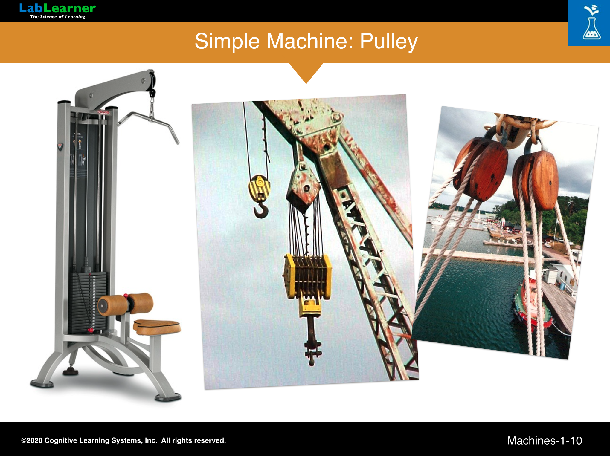
This slide shows several examples of pulleys. Perhaps nowhere has the application of pulley technology been so elaborately developed as in the rigging systems of the large sailing ships of history.
Work and Simple Machines: Relevant LabLearner CELL Units
Preschool
Intermediate+
Primary
Intermediate+
Intermediate
Potential & Kinetic Energy
Simple Machines
Open Inquiry: The Pendulum
Friction